:link: Tags: CS
Introduction to C4-PlantUML with Examples
Introduction
This is a tutorial with examples for C4-PlantUML, which is an easy to learn and developer-friendly approach to architecture diagramming. i.e. simple code -> diagram
As the name suggest, C4-PlantUML is a combination of C4 model and PlantUML . It can simply change diagrams
from

to

Components
A C4-PlantUML diagram is made up of zero or more entities, boundaries, and relationships.
Relationship
A Relationship is a line/arrow / bidirectional arrow between 2 entities, representing how these two entities are connected.
:blue_book: Can represent relationships like this app loads data from the database, I report to my boss, this system works with that app, etc.

Boundary
A Boundary is a dotted rectangle that shows the limit of a system, i.e. the entities in the boundary belong to one category.
:blue_book: Can represent relationships like This UI, and this database belongs to Twitter, or these three products belong to my department.

Entity
Entities are the objects/nodes/elements in the diagram. It is usually a predefined solid rectangle with info in it but can have other shapes.
:blue_book: Can represent objects like a database, a user, a reporting system, a UI etc.
- They can have different colours/shapes (by default, "external" entities are grey)
- The most common entity types are Internal/External Person, Internal/External System, Internal/External Container, and Internal/External DB.
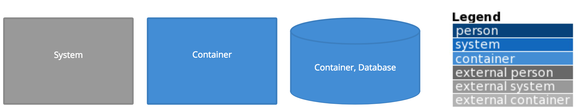
:orange_book: Note: The Full list of supported entities/relations is attached at the end of the notes
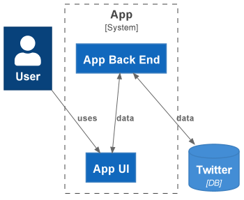
Example
A C4-PlantUML diagram is a logical combination of these three components. For example, this diagram shows the relationship between Twitter users, Twitter App and Twitter database.
Getting Started
Setting Up in IDE
Intellij
Please download Graphviz and PlantUML Integration. See this link for more details.
VS Code
Please add snippets for C4-PlantUML. See this link for more details.
Setting Up a new .puml File
- Create a new
.pumlfile

- Add
@startumlat the start of the file, and@endumlat the end of the file - To use the up-to-date version, including the latest plantuml-stdlib by adding:
!include https://raw.githubusercontent.com/plantuml-stdlib/C4-PlantUML/master/C4_Container.puml - (Optional) Add the diagram title
@startuml
!include https://raw.githubusercontent.com/plantuml-stdlib/C4-PlantUML/master/C4_Container.puml
title Example Title
@enduml
An example blank page with a title

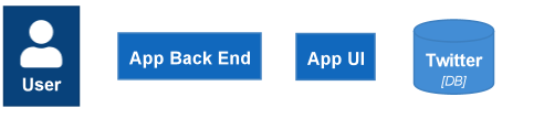
Entity
To add entities, we need to specify the
- Entity type – would have different shapes and colours
- Entity ID/alias – need to be unique
- Label – the name of the entity display in the diagram
For some entities like Container, we can add an optional tag.
:blue_book: For example, we can create some blocks that represent users, twitter database, Twitter app UI and Twitter app back end
...
Person(admin, "User")

System(backend, "App backend")
System(ui, "App UI")

ContainerDb(twitter, "Twitter", "DB")
...
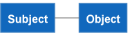
Relationship
The relationship can be a line/arrow / bidirectional arrow.
The starting point is called Subject, and the ending point is Object.
...
System(subject, "Subject")
System(object, "Object")
...
Line
To add relationships, we need to specify the
- from: the starting point / the subject of the relationship.
- to: the ending point / the object of the relationship.
- :orange_book: Note: Description/tag: Description or tag text on the line is NOT supported
Short Line
...
System(subject, "Subject")
System(object, "Object")

subject - object
...
Longline
...
System(subject, "Subject")
System(object, "Object")

subject -- object
...
Arrow
To add arrows, we need to specify the
- from: the starting point / the subject of the relationship.
- to: the ending point / the object of the relationship.
- Description – Some text that describes the relation.
- (optional) Tag
Relationship Types
- Rel(from, to, label, ?tag)
- BiRel (bidirectional relationship)
You can force the direction of a relationship by using:
- Rel_U, Rel_Up
- Rel_D, Rel_Down
- Rel_L, Rel_Left
- Rel_R, Rel_Right
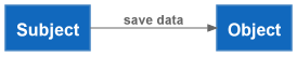
We can add arrows / bidirectional arrows between the "subject" entity and the "object" entity.
Basic arrow
...
System(subject, "Subject")
System(object, "Object")

Rel(subject, object, "save data")
...
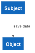
Down arrow
...
System(subject, "Subject")
System(object, "Object")

Rel_D(subject, object, "save data")
...
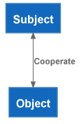
Bidirectional arrow
...
System(subject, "Subject")
System(object, "Object")

BiRel(subject, object, "Cooperate")
...
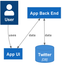
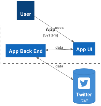
:blue_book: For example, for the Twitter system, we can represent the relationship of
- User read twitter UI
- Twitter UI send & fetch data to & from the Twitter app backend
- Twitter app backend send & fetch data to & from the Twitter database
...
Person(admin, "User")
System(backend, "App Back End")
System(ui, "App UI")
ContainerDb(twitter, "Twitter", "DB")

Rel(admin, ui, "uses")
BiRel(backend, ui, "data")
BiRel(backend, twitter, "data")
...
Boundary
To add boundaries, we need to build a block that specifies the
- boundary ID/alias – need to be unique
- Description – Some text that describes the relation.
We define the entities (systems, containers, DB, etc.) that belong to that category in the block.
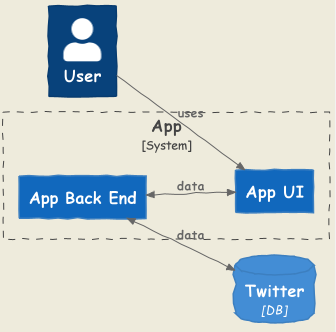
:blue_book: For example, for the Twitter system mentioned in previous examples, Twitter App UI and Twitter App Back End both belong to Twitter App and can be put into the same block in the user-app diagram.
...

Person(admin, "User")
System_Boundary(app, "App") {
    System(backend, "App Back End")
    System(ui, "App UI")
}
ContainerDb(twitter, "Twitter", "DB")
...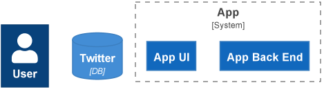
Example
Now, let us put the entities, relationships and boundaries together.
...
Person(admin, "User")
System_Boundary(app, "App") {
    System(backend, "App backend")
    System(ui, "App UI")
}
ContainerDb(twitter, "Twitter", "DB")

Rel(admin, ui, "uses")
BiRel(backend, ui, "data", "HTTPS")
BiRel(backend, twitter, "data", "HTTPS")
...
Advanced Options
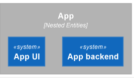
Nested Entities
Similar to how we define boundaries, we can put an entity into another (i.e. nested)
For example, we can put system backend and ui into app with
Container_Ext(app, "App", "Nested Entities") {
    System(backend, "App backend")
    System(ui, "App UI")
}
Icon/sprite
Entities can also be decorated with icons/sprites using the sprite parameter. To use icons, we can include/import the icon from the tupadr3 library.
:blue_book: In the previous example, we can add a Twitter icon to the database by adding
ContainerDb(twitter, "Twitter", "DB", \$sprite="twitter_square")
Complete code
…
!define FONTAWESOME https://raw.githubusercontent.com/tupadr3/plantuml-icon-font-sprites/master/font-awesome-5
!include FONTAWESOME/twitter_square.puml
Person(admin, "User")
System_Boundary(app, "App") {
System(backend, "App Back End")
System(ui, "App UI")
}
ContainerDb(twitter, "Twitter", "DB", \$sprite="twitter_square")
Rel(admin, ui, "uses")
BiRel(backend, ui, "data")
BiRel(backend, twitter, "data")
…
See the tupadr3 link and the C4-plantuml doc link for more info.
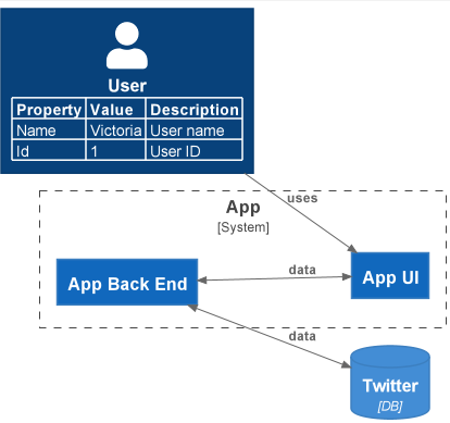
Element properties (add tables)
A model can be extended with (a table of) properties that concrete deployments or more detailed concepts can be documented:
-
SetPropertyHeader(col1Name, col2Name, ?col3Name, ?col4Name): The properties table can have up to 4 columns. The default header uses the column names "Name", "Description". -
WithoutPropertyHeader()If no header is used, then the second column is bold. -
AddProperty(col1, col2, ?col3, ?col4)(All columns of) a property which will be added to the next element.
:blue_book: For example, we can add a table to the Twitter user entity by adding
SetPropertyHeader("Property","Value", "Description")
AddProperty("Name", "Victoria", "User name")
AddProperty("Id", "1", "User ID")
Complete code
...
SetPropertyHeader("Property","Value", "Description")
AddProperty("Name", "Victoria", "User name")
AddProperty("Id", "1", "User ID")
Person(admin, "User")
System_Boundary(app, "App") {
    System(backend, "App Back End")
    System(ui, "App UI")
}
ContainerDb(twitter, "Twitter", "DB")

Rel(admin, ui, "uses")
BiRel(backend, ui, "data")
BiRel(backend, twitter, "data")
...
Colour Customisation
We can
- custom the colour all relationships via
UpdateRelStyle() - custom the colour of a specific entity type (like system, person, container etc.) via
UpdateElementStyle()
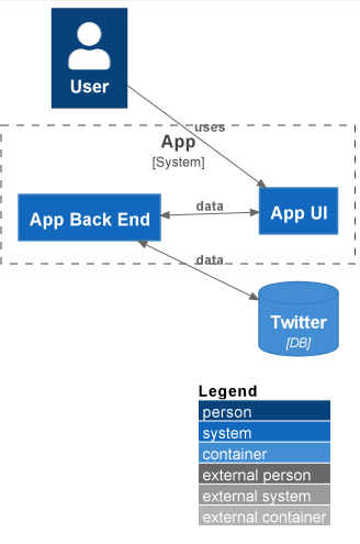
If we add SHOW_LEGEND(), the legend of existing elements will be updated too.
UpdateElementStyle:
- background colour
bgColor - text colour
fontColor - border colour
borderColor
UpdateRelStyle:
- line colour:
lineColor - text colour:
textColor
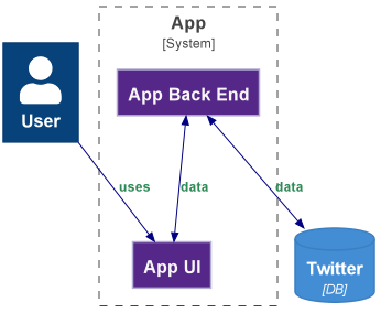
For example, we can custom all system entities to
- background colour: Purple "#542788"
- text colour: White "#f7f7f7"
- border colour: Light purple "#b2abd2"
!\$COLOR_BG = "#542788"
!\$COLOR_FONT = "#f7f7f7"
!\$COLOR_BORDER = "#b2abd2"
UpdateElementStyle("system", \$bgColor=\$COLOR_BG, \$fontColor=\$COLOR_FONT, \$borderColor=\$COLOR_BORDER)
we can custom all relationships to
- line colour: Navy "#000080"
- text colour: Sea green "#2E8B57"
!\$COLOR_REL_LINE = "#000080"
!\$COLOR_REL_TEXT = "#2E8B57"
UpdateRelStyle(\$lineColor=\$COLOR_REL_LINE, \$textColor=\$COLOR_REL_TEXT)
and finally, to update the legend, we can add
UpdateElementStyle()Complete code
…
!\$COLOR_BG = "#542788"
!\$COLOR_FONT = "#f7f7f7"
!\$COLOR_BORDER = "#b2abd2"
UpdateElementStyle("system", \$bgColor=\$COLOR_BG, \$fontColor=\$COLOR_FONT, \$borderColor=\$COLOR_BORDER)
!\$COLOR_REL_LINE = "#000080"
!\$COLOR_REL_TEXT = "#2E8B57"
UpdateRelStyle(\$lineColor=\$COLOR_REL_LINE, \$textColor=\$COLOR_REL_TEXT)
Person(admin, "User")
System_Boundary(app, "App") {
System(backend, "App Back End")
System(ui, "App UI")
}
ContainerDb(twitter, "Twitter", "DB")
Rel(admin, ui, "uses")
BiRel(backend, ui, "data")
BiRel(backend, twitter, "data")
…
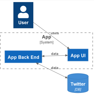
Layout
We can add a layout (like LAYOUT_TOP_DOWN()) at anywhere of the puml file and change the layout to make it easy and reuseable to create nice and useful diagrams.
For example, you can use a top-down style layout via adding LAYOUT_TOP_DOWN()
@startuml
!include https://raw.githubusercontent.com/plantuml-stdlib/C4-PlantUML/master/C4_Container.puml

LAYOUT_TOP_DOWN()
...
See this link for all options
LAYOUT_TOP_DOWN()/LAYOUT_LEFT_RIGHT()
These two layouts conflict, so we can only use one of them.
LAYOUT_TOP_DOWN()

LAYOUT_LEFT_RIGHT()
LAYOUT_WITH_LEGEND()
When added – annotations (person, system, container etc. ) are not displayed in entities, and the diagram has a legend.
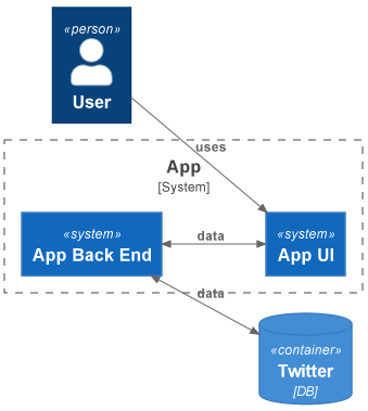
When not added – annotations (person, system, container etc. ) are displayed in a double angle brackets symbol (like <<system>>) in the entities, and the diagram has no legends.
LAYOUT_AS_SKETCH
Playful hand-drawn style : ) :pencil2:
All Supported Diagram Elements
Please see the complete list of supported diagram elements here
Reference
-
GitHub. 2021. plantuml-stdlib/C4-PlantUML. [online] Available at: https://github.com/plantuml-stdlib/C4-PlantUML [Accessed 3 July 2021].
-
GitHub. 2021. plantuml-stdlib/C4-PlantUML. [online] Available at: https://github.com/plantuml-stdlib/C4-PlantUML/blob/master/samples/C4CoreDiagrams.md [Accessed 3 July 2021].
-
Crashedmind.github.io. 2021. 2. Using PlantUML Stdlib C4 Lightweight Software Architecture Description Method — The Hitchhiker’s Guide to PlantUML documentation. [online] Available at: https://crashedmind.github.io/PlantUMLHitchhikersGuide/C4/C4Stdlib.html [Accessed 3 July 2021].
-
GitHub. 2021. tupadr3/plantuml-icon-font-sprites. [online] Available at: https://github.com/tupadr3/plantuml-icon-font-sprites [Accessed 3 July 2021].
-
Kang, J., 2021. Diagramming software architecture using C4 model and C4-PlantUML – LINE ENGINEERING. [online] LINE ENGINEERING. Available at: https://engineering.linecorp.com/en/blog/diagramming-software-architecture-using-c4-model-and-c4-plantuml/ [Accessed 4 July 2021].
-
C4model.com. 2021. The C4 model for visualising software architecture. [online] Available at: https://c4model.com/ [Accessed 4 July 2021].